
Call Us: +91-7972969901

Call Us: +91-7972969901
DIMENSIONS

DIMENSIONS

SPECIFICATIONS
Metric
| Order No. | Range | Accuracy | Stem dia. | Stem | Spindle end | Special features |
|---|---|---|---|---|---|---|
| 148-503 |
0 – 13mm |
±2µm |
9.5mm |
Plain |
Flat |
Standard |
| 148-513 | Stainless steel throughout | |||||
| 148-508 | W/ clamp nut |
Standard |
||||
| 148-506 | Plain* | |||||
| 148-504 | W/ clamp nut* | |||||
| 148-853 | Plain | Spherical (SR4) | ||||
| 148-854 | W/ clamp nut* | |||||
| 148-863 | Plain |
Flat |
Reverse reading | |||
| 148-864 | W/ clamp nut* | |||||
| 148-518** | W/ clamp nut | Stainless steel throughout | ||||
| 148-858** | W/ clamp nut | Spherical (SR4) | Standard | |||
| 148-866** | Plain* | Flat | Reverse reading | |||
| 148-856** | Plain* | Spherical (SR4) | Standard | |||
| 148-868** | W/ clamp nut | Flat | Reverse reading |
* with spindle lock ** made-to-order models
Inch
| Order No. | Range | Accuracy | Stem dia. | Stem | Spindle end | Special features |
|---|---|---|---|---|---|---|
| 148-501 |
0 – .5″ |
±.0001″ |
.375″ |
Plain |
Flat |
Standard |
| 148-511** | Stainless steel throughout | |||||
| 148-507** | W/ clamp nut |
Standard |
||||
| 148-505 | Plain* | |||||
| 148-502 | W/ clamp nut* | |||||
| 148-851 | Plain | Spherical (SR4) | ||||
| 148-852 | W/ clamp nut* | |||||
| 148-861 | Plain | Flat | Reverse reading | |||
| 148-862 | W/ clamp nut* |
* with spindle lock ** made-to-order models
Technical Data
Graduation: 0.01mm or .001″
Spindle pitch: 0.5mm or .025″
DIMENSIONS


DIMENSIONS

SPECIFICATIONS
| Order No. | Description | Applicable holding stem dia. | Magnetic force | Remarks |
|---|---|---|---|---|
| 7010-10 | Magnetic stand | ø6mm, ø8mm | Approx. 600N | — |
| 7010S-10 | Magnetic stand | ø4mm, ø8mm, ø9.53mm (3/8”) | Approx. 600N | — |
| 7011-10 | Magnetic stand | ø6mm, ø8mm | Approx. 600N | With fine adjustment |
| 7011S-10 | Magnetic stand | ø4mm, ø8mm, ø9.53mm (3/8”) | Approx. 600N | With fine adjustment |
| 7012-10 | Magnetic stand | ø6mm, ø8mm, ø9.53mm (3/8”) | Approx. 600N | — |
| 7014-10 | Mini magnetic stand | ø6mm, ø8mm | Approx. 150N | Without magnet ON/OFF |
| 7014E-10 | Mini magnetic stand | ø4mm, ø9.53mm (3/8”) | Approx. 150N | Without magnet ON/OFF |
| 7033B | Universal magnetic stand | ø6, ø8mm, ø9.53mm (3/8”) | Approx. 600N | With mechanical locking system |
| 7031B | Universal magnetic stand | ø6, ø8mm, ø9.53mm (3/8”) | Approx. 300N | With mechanical locking system |
| 7032B | Universal magnetic stand | ø6, ø8mm, ø9.53mm (3/8”) | Approx. 600N | With mechanical locking system |

Note: The dial indicator and protection cover are optional.
SPECIFICATIONS
Metric
| Order No. | Range | Parallelism | Measuring force | Recommended dial indicator (optional) |
|---|---|---|---|---|
| 201-101 | 0 – 25mm | 5µm | 15N±3N | 2046SB (0.01mm reading), 2109SB-10 (0.001mm reading) |
| 201-102 | 25 – 50mm | 5µm | 15N±3N | 2046SB (0.01mm reading), 2109SB-10 (0.001mm reading) |
| 201-103 | 50 – 75mm | 5µm | 15N±3N | 2046SB (0.01mm reading), 2109SB-10 (0.001mm reading) |
| 201-104 | 75 – 100mm | 5µm | 15N±3N | 2046SB (0.01mm reading), 2109SB-10 (0.001mm reading) |
| 201-105 | 100 – 125mm | 5µm | 15N±3N | 2046SB (0.01mm reading), 2109SB-10 (0.001mm reading) |
| 201-106 | 125 – 150mm | 5µm | 15N±3N | 2046SB (0.01mm reading), 2109SB-10 (0.001mm reading) |
| 201-107 | 150 – 175mm | 5µm | 15N±3N | 2046SB (0.01mm reading), 2109SB-10 (0.001mm reading) |
| 201-108 | 175 – 200mm | 5µm | 15N±3N | 2046SB (0.01mm reading), 2109SB-10 (0.001mm reading) |
| 201-109 | 200 – 225mm | 5µm | 15N±3N | 2046SB (0.01mm reading), 2109SB-10 (0.001mm reading) |
| 201-110 | 225 – 250mm | 5µm | 15N±3N | 2046SB (0.01mm reading), 2109SB-10 (0.001mm reading) |
| 201-111 | 250 – 275mm | 5µm | 15N±3N | 2046SB (0.01mm reading), 2109SB-10 (0.001mm reading) |
| 201-112 | 275 – 300mm | 5µm | 15N±3N | 2046SB (0.01mm reading), 2109SB-10 (0.001mm reading) |
Inch
| Order No. | Range | Parallelism | Measuring force | Recommended dial indicator (optional) |
|---|---|---|---|---|
| 201-151 | 0 – 1” | .0002” | 15N±3N | 2803SB-10 (.0001” reading) |
| 201-152 | 1 – 2” | .0002” | 15N±3N | 2803SB-10 (.0001” reading) |
| 201-153 | 2 – 3” | .0002” | 15N±3N | 2803SB-10 (.0001” reading) |
| 201-154 | 3 – 4” | .0002” | 15N±3N | 2803SB-10 (.0001” reading) |
| 201-155 | 4 – 5” | .0002” | 15N±3N | 2803SB-10 (.0001” reading) |
| 201-156 | 5 – 6” | .0002” | 15N±3N | 2803SB-10 (.0001” reading) |
| 201-157 | 6 – 7” | .0002” | 15N±3N | 2803SB-10 (.0001” reading) |
| 201-158 | 7 – 8” | .0002” | 15N±3N | 2803SB-10 (.0001” reading) |
| 201-159 | 8 – 9” | .0002” | 15N±3N | 2803SB-10 (.0001” reading) |
| 201-160 | 9 – 10” | .0002” | 15N±3N | 2803SB-10 (.0001” reading) |
| 201-161 | 10 – 11” | .0002” | 15N±3N | 2803SB-10 (.0001” reading) |
| 201-162 | 11 – 12” | .0002” | 15N±3N | 2803SB-10 (.0001” reading) |
*1: Measuring force is that force present before an indicator is installed and is determined at the point where the spindle is retracted 1mm from the rest position.
DIMENSIONS

Optional accessories
Dial indicator
Dial protection cover: No.21DZA000
Refer to page C-45 for details.
Recommended dial indicators
No.2046SB: Dial indicator (Graduation: 0.01mm)
No.2109SB-10: Dial indicator (Graduation: 0.001mm)
Internal measurement

SPECIFICATIONS
Metric
| Order No. | Range | Graduation | Range of opening*1 | Dial face | Accuracy | Measuring force |
|---|---|---|---|---|---|---|
| 209-125 | 6 – 18mm | 0.01mm | 5.8 – 18.2mm | 0-100-100 | ±40µm | 2.0N or less |
| 209-126 | 10 – 22mm | 0.01mm | 9.8 – 22.2mm | 0-100-100 | ±40µm | 2.0N or less |
| 209-127 | 20 – 32mm | 0.01mm | 19.8 – 32.2mm | 0-100-100 | ±40µm | 2.0N or less |
| 209-155 | 5 – 15mm | 0.01mm | 4.8 – 15.2mm | 0-100 | ±30µm | 2.0N or less |
| 209-156 | 10 – 20mm | 0.01mm | 9.8 – 20.2mm | 0-100 | ±30µm | 2.0N or less |
| 209-175 | 10 – 30mm | 0.01mm | 9.8 – 30.2mm | 0-100-100 | ±40µm | 2.0N or less |
| 209-176 | 20 – 40mm | 0.01mm | 19.8 – 40.2mm | 0-100-100 | ±40µm | 2.0N or less |
*1: Datum point setting is required (Reference gage available as an optional accessory).
*2: Range of opening is a value for reference. Accuracy is not guaranteed if the Dial Caliper Gage is used beyond the measuring range.
* Please note that this Dial Caliper Gage is only provided with standard models. Special size and special specification models are not supported.
DIMENSIONS

| Order No. | A | B |
|---|---|---|
| 209-125 | 1.1 | 1.1 |
| 209-126 | 2.3 | 2.7 |
| 209-127 | 8.0 | 4.4 |

| Order No. | A | B | L | T |
|---|---|---|---|---|
| 209-155 | 2.2 | 2.2 | 26 | 1.2 |
| 209-156 | 5.5 | 5.5 | 28 | 1.5 |

| Order No. | A | B | T |
|---|---|---|---|
| 209-175 | 5.5 | 5.5 | 1.5 |
| 209-176 | 10 | 10 | 2.0 |
Standard Type

High Accuracy Type

Standard Type

Lightweight Type (integrated molding of the bezel)

Lens thickness measurement

Tube thickness measurement

Groove depth measurement

Usage examples
Measuring paper thickness

Measuring thickness of a human hair

DIMENSIONS

Unit: mm
Optional Accessories
905338: SPC cable (1m) for digital models
905409: SPC cable (2m) for digital models
02AZD790F: SPC cable for U-WAVE (160mm)
Digimatic Mini-Processor DP-1VR
Refer to page A-13 for details.
Input Tool
Convenient Interface Input Tools which enable the conversion of measurement data to keyboard signals and directly input them to cells in off-the-shelf spreadsheet software such as Excel.
(Refer to pages A-5 to A-6 for details.)
DIMENSIONS

Application examples

Note:Parallelism between the flat point and anvil
547-313: 10μm
7313: 5μm Concave lens Ball
DIMENSIONS

DIMENSIONS

Styli (for Metric Models Only*)
* Except for universal type dial test indicator (513-304G).

ø0.5mm ball-point

190547 (L=14.7mm)
190549 (L=20.9mm)
190654 (L=22.3mm)
190656 (L=44.5mm)
ø0.7mm ball-point

190548 (L=14.7mm)
190550 (L=20.9mm)
190653 (L=22.3mm)
190655 (L=44.5mm)
ø1mm ball-point (Carbide)

21CZA044 (L=12.8mm)
103017 (L=14.7mm)
103013 (L=20.9mm)
137558 (L=22.3mm)
137746 (L=36.8mm)
136235 (L=44.5mm)
ø2mm ball-point (Carbide)

21CZA036 (L=12.8mm)
103010 (L=14.7mm)
103006 (L=20.9mm)
137557 (L=22.3mm)
129949 (L=36.8mm)
136013 (L=44.5mm)
ø2mm ball-point (Ruby)

21CZA212 (L=12.8mm)
21CZA209 (L=14.7mm)
21CZA201 (L=20.9mm)
21CZA210 (L=22.3mm)
21CZA211 (L=44.5mm)
ø3mm ball-point (Carbide)

21CZA045 (L=12.8mm)
103018 (L=14.7mm)
103014 (L=20.9mm)
137559 (L=22.3mm)
137747 (L=36.8mm)
136236 (L=44.5mm)
Spanner

Stems with Knurled Clamp Ring

Swivel Clamps

Holding Bars

Universal Holder

21CZA233 (ø8mm stem)
21CZA231 (.25″ DIA. stem)
21CZA229 (ø6mm stem)
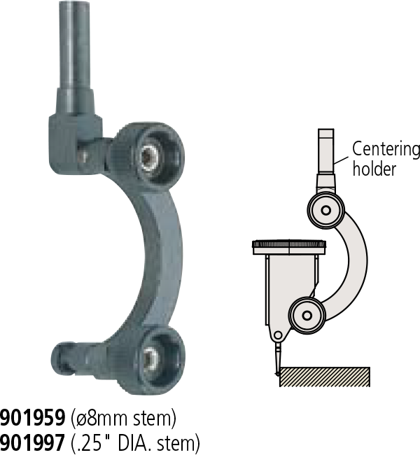
Centering Holder


SPECIFICATIONS

DIMENSIONS


There are two types of Mitutoyo Dial Test Indicator: The non-clutch type (without a clutch lever) and the clutch type (with a two-position clutch lever)

In the non-clutch type, although the contact point may move either in the upward or downward direction, the pointer always rotates clockwise. In the clutch type, if the clutch lever is set in one position the contact point moves in the upward direction and the pointer rotates clockwise. Conversely, if the lever is set in the other position the contact point moves in the downward direction and the pointer rotates counterclockwise.
Set Configuration: Metric

Set Configuration: Inch


SPECIFICATIONS

DIMENSIONS

Set Configuration: Metric

Set Configuration: Inch

Optional Accessories
––––––: Swivel clamps (See page F-63.)
––––––: Holding bars (See page F-63.)
––––––: Stems (See page F-63.)
102824: Stylus, ø1mm ball contact (carbide)
102825: Stylus, ø2mm ball contact (carbide)
102826: Stylus, ø3mm ball contact (carbide)