
Call Us: +91-7972969901

Call Us: +91-7972969901

SPECIFICATIONS
Metric
| Order No. | Graduation | Range (range/rev) | Accuracy | Repeat- ability | Dial reading | Measuring force | ||||
|---|---|---|---|---|---|---|---|---|---|---|
| w/ lug | Flat-back | Overall | Retrace | 1/10 Rev | 1 Rev | |||||
| 2050S | 2050SB | 0.01mm | 20mm (1mm) | 20µm | 5µm | 8µm | 15µm | 4µm | ±0-100 | 2.0N or less |
| 2050S-60 | 2050SB-60 | 0.01mm | 20mm (1mm) | 20µm | 5µm | 8µm | 15µm | 4µm | ±0-100 | 2.5N or less |
| 2050S-19 | 2050SB-19 | 0.01mm | 20mm (1mm) | 20µm | 5µm | 8µm | 15µm | 4µm | ±0-100 | 2.0N or less |
| 2320S-10 | 2320SB-10 | 0.01mm | 20mm (1mm) | 20µm | 5µm | 8µm | 15µm | 4µm | ±0-100 | 2.0N or less |
| 2052S | 2052SB | 0.01mm | 30mm (1mm) | 25µm | 7µm | 10µm | 15µm | 5µm | ±0-100 | 2.5N or less |
| 2052S-19 | 2052SB-19 | 0.01mm | 30mm (1mm) | 25µm | 7µm | 10µm | 15µm | 5µm | ±0-100 | 2.5N or less |
| 2330S-10 | 2330SB-10 | 0.01mm | 30mm (1mm) | 25µm | 7µm | 10µm | 15µm | 5µm | ±0-100 | 2.5N or less |
| 2952S | 2952SB | 0.01mm | 30mm (1mm) | 25µm | 7µm | 10µm | 15µm | 5µm | 100-0 | 2.5N or less |
*1 2050S-60 and 2050SB-60 are waterproof types that use a rubber bellows to cover the spindle. Please note that the outer diameter of the bellows (ø9.5) is larger than that of the stem (ø8).
*2 Completed products inspection is performed in the vertical position (contact point downward) and the stated accuracy is guaranteed.
Inch
| Order No. | Graduation | Range (range/rev) | Accuracy | Repeat- ability | Dial reading | Measuring force | ||
|---|---|---|---|---|---|---|---|---|
| w/ lug | Flat-back | First 1 Rev / 2.5 Rev / 10 Rev | Retrace | |||||
| 2416S | 2416SB | .001” | 1” (.1”) | ±.001” / ±.001” / ±.002” | .0002” | ±.0002” | ±0-100 | 1.8N or less |
| 2416S-06 | 2416SB-06 | .001” | 1” (.1”) | ±.001” / ±.001” / ±.002” | .0002” | ±.0002” | ±0-100 | 1.8N or less |
| 2416S-10 | 2416SB-10 | .001” | 1” (.1”) | ±.001” / ±.001” / ±.002” | .0002” | ±.0002” | ±0-100 | 1.8N or less |
| 2417S | 2417SB | .001” | 1” (.1”) | ±.001” / ±.001” / ±.002” | .0002” | ±.0002” | 0-50-0 | 1.8N or less |
| 2424S-19 | 2424SB-19 | .001” | 2” (.1”) | ±.001” / ±.001” / ±.002” /
±.003” (First 20Rev) |
.00033” | ±.0002” | ±0-100 | 2.5N or less |
| 2776S | 2776SB | .0005” | 1” (.05”) | ±.0005” / ±.0005” / ±.0015” /
±.002” (First 20Rev) |
.0002” | ±.0001” | ±0-50 | 2.5N or less |
| 2904S | 2904SB | .001” | 1” (.1”) | ±.001” / ±.001” / ±.002” | .0002” | ±.0002” | 100-0 | 1.8N or less |
* Completed products inspection is performed in the vertical position (contact point downward) and the stated accuracy is guaranteed.
FEATURES
Metric

Inch

DIMENSIONS

| Order No. | A | B | C | D | E | F | G | H | I |
|---|---|---|---|---|---|---|---|---|---|
| 2050S | 38.8 | 75.2 | 57 | 17.7 | 20 | 16.9 | 29.8 | 52 | 7.6 |
| 2050S-60 | 59.8 | 87.2 | 57 | 17.7 | 20 | 12.3 | 46.4 | 52 | 7.6 |
| 2050S-19 | 38.8 | 75.2 | 57 | 17.7 | 20 | 16.9 | 29.8 | 52 | 7.6 |
| 2320S-10 | 38.8 | 75.2 | 57 | 17.7 | 20 | 16.9 | 29.8 | 52 | 7.6 |
| 2052S | 38.8 | 88.7 | 57 | 17.7 | 20 | 16.9 | 43.3 | 52 | 7.6 |
| 2052S-19 | 38.8 | 88.7 | 57 | 17.7 | 20 | 16.9 | 43.3 | 52 | 7.6 |
| 2330S-10 | 38.8 | 88.7 | 57 | 17.7 | 20 | 16.9 | 43.3 | 52 | 7.6 |
| 2952S | 38.8 | 88.7 | 57 | 17.7 | 20 | 16.9 | 43.3 | 52 | 7.6 |
| Order No. | A | B | C | D | E | F | G | H | I |
|---|---|---|---|---|---|---|---|---|---|
| 2416S | 38.9 | 76.8 | 57 | 17.7 | 19 | 13.6 | 34.7 | 52 | 7.6 |
| 2416S-06 | 38.9 | 76.8 | 57 | 17.7 | 19 | 13.6 | 34.7 | 52 | 7.6 |
| 2416S-10 | 38.9 | 76.8 | 57 | 17.7 | 19 | 13.6 | 34.7 | 52 | 7.6 |
| 2417S | 38.9 | 76.8 | 57 | 17.7 | 19 | 13.6 | 34.7 | 52 | 7.6 |
| 2424S-19 | 118 | 142.5 | 57 | 17.7 | 20.9 | 54.3 | 59.7 | 52 | 9.5 |
| 2776S | 38.9 | 76.8 | 57 | 17.7 | 19 | 13.6 | 34.7 | 52 | 7.6 |
| 2904S | 38.9 | 76.8 | 57 | 17.7 | 19 | 13.6 | 34.7 | 52 | 7.6 |

DIMENSIONS

* When installing an optional back (refer to page F-55 for details) please separately prepare 4 fixing screws
(Order No. 546666: Self-tapping screw only for resin).
Do not apply a tightening torque of more than 20N-cm in order to avoid stripping the screw threads.
* An optional lifting lever, release or outer frame clamp cannot be installed
| Order No. | A | B | C | D | F | G | H | I |
|---|---|---|---|---|---|---|---|---|
| 2971TB | 43.2 | 65.6 | 57 | 16.5 | 21 | 16.8 | 55 | 7.6 |
| 2972TB | 43.2 | 66 | 57 | 16.5 | 21 | 17.2 | 55 | 7.6 |
| 2973TB | 43.2 | 66.3 | 57 | 16.5 | 21 | 17.5 | 55 | 7.6 |
| 2976TB | 43.2 | 64.7 | 57 | 16.5 | 20.3 | 15.9 | 55 | 7.6 |
| 2977TB | 43.2 | 65 | 57 | 16.5 | 20.3 | 16.2 | 55 | 7.6 |
| 2978TB | 43.2 | 65.3 | 57 | 16.5 | 20.3 | 16.5 | 55 | 7.6 |
SPECIFICATIONS
Metric
| Order No. | Graduation | Range (range/rev) | Accuracy | Repeat- ability | Dial reading | Measuring force | ||||
|---|---|---|---|---|---|---|---|---|---|---|
| w/ lug | Flat-back | Overall | Retrace | 1/10 Rev | 1 Rev | |||||
| — | 2971TB | 0.01mm | 0.5mm (0.7mm) | 8µm | 3µm | 5µm | — | 3µm | 25-0-25 | 1.4N or less |
| — | 2972TB | 0.01mm | 1mm (1.4mm) | 8µm | 3µm | 5µm | — | 3µm | 50-0-50 | 1.4N or less |
| — | 2973TB | 0.02mm | 1.6mm (2mm) | 16µm | 6µm | 8µm | — | 5µm | 80-0-80 | 1.4N or less |
* Completed products inspection is performed in the vertical position (contact point downward) and the stated accuracy is guaranteed.
Inch
| Order No. | Graduation | Range (range/rev) | Accuracy | Repeat- ability | Dial reading | Measuring force | ||
|---|---|---|---|---|---|---|---|---|
| w/ lug | Flat-back | First 1 Rev / 2.5 Rev / 10 Rev | Retrace | |||||
| — | 2976TB | .0005” | .02” (.028”) | ±.0005″/–/– | .00016″ | ±.0001” | 10-0-10 | 1.4N or less |
| — | 2977TB | .0005” | .04” (.055”) | ±.0005″/–/– | .00016″ | ±.0001″ | 20-0-20 | 1.4N or less |
| — | 2978TB | .001” | .06” (.079”) | ±.001″/–/– | .0002” | ±.0002” | 30-0-30 | 1.4N or less |
* Completed products inspection is performed in the vertical position (contact point downward) and the stated accuracy is guaranteed.
FEATURES
Metric

Inch


DIMENSIONS

Note 1: Dimensions of the inch (ANSI/AGD Type) dial indicator partly differ from those of the metric (ISO/JIS Type) indicator.
Note 2: Inch (ANSI/AGD Type) dial indicators are provided with a stem of 3/8″ dia. and #4- 48UNF thread mount for the contact point.
| Order No. | A | B | C | D | E | F | G | H | I |
|---|---|---|---|---|---|---|---|---|---|
| 2929S-60 | 48.8 | 70 | 57 | 17.7 | 20 | 12.3 | 29.2 | 52 | 7.6 |
| 2900S-70 | 48.8 | 67 | 57 | 17.7 | 20 | 12.3 | 26.2 | 52 | 7.6 |
| Order No. | A | B | C | D | E | F | G | H | I |
|---|---|---|---|---|---|---|---|---|---|
| 2910S-72 | 48.8 | 51.2 | 57 | 17.7 | 19 | 13.6 | 9.1 | 52 | 7.6 |
SPECIFICATIONS
Metric
| Order No. | Graduation | Range (range/rev) | Accuracy | Repeat- ability | Dial reading | Measuring force | ||||
|---|---|---|---|---|---|---|---|---|---|---|
| w/ lug | Flat-back | Overall | Retrace | 1/10 Rev | 1 Rev | |||||
| 2929S-60 | 2929SB-60 | 0.01mm | 0.8mm (1mm) | 8µm | 3µm | 5µm | — | 3µm | 40-0-40 | 2.0N or less |
| 2900S-70 | 2900SB-70 | 0.001mm | 0.08mm (0.1mm) | 3µm | 2µm | 2µm | — | 0.5µm | 40-0-40 | 2.0N or less |
* Completed products inspection is performed in the vertical position (contact point downward) and the stated accuracy is guaranteed.
Inch
| Order No. | Graduation | Range (range/rev) | Accuracy | Repeat- ability | Dial reading | Measuring force | ||
|---|---|---|---|---|---|---|---|---|
| w/ lug | Flat-back | First 1 Rev / 2.5 Rev / 10 Rev | Retrace | |||||
| 2910S-72 | 2910SB-72 | .0001” | .008” / .01” | ±.0001” / — / — | .0001” | ±.00003” | 4-0-4 | 2.5N or less |
* Completed products inspection is performed in the vertical position (contact point downward) and the stated accuracy is guaranteed.
FEATURES
Metric

Inch


DIMENSIONS

Note 1: Dimensions of the inch (ANSI/AGD Type) dial indicator partly differ from those of the metric (ISO/JIS Type) indicator.
Note 2: Inch (ANSI/AGD Type) dial indicators are provided with a stem of 3/8″ dia. and #4- 48UNF thread mount for the contact point.
| Order No. | A | B | C | D | E | F | G | H | I |
|---|---|---|---|---|---|---|---|---|---|
| 2928S | 48.8 | 65.2 | 57 | 17.7 | 20 | 16.9 | 19.8 | 52 | 7.6 |
| 2929S | 48.8 | 65.2 | 57 | 17.7 | 20 | 16.9 | 19.8 | 52 | 7.6 |
| 2929S-62 | 48.8 | 65.2 | 57 | 17.7 | 20 | 16.9 | 19.8 | 52 | 7.6 |
| 2959S | 48.8 | 65.2 | 57 | 17.7 | 20 | 16.9 | 19.8 | 52 | 7.6 |
| 2900S-10 | 48.8 | 66 | 57 | 17.7 | 20 | 16.9 | 20.6 | 52 | 7.6 |
| 2900S-72 | 48.8 | 66 | 57 | 17.7 | 20 | 16.9 | 20.6 | 52 | 7.6 |
| 2901S-10 | 48.8 | 66.1 | 57 | 17.7 | 20 | 16.9 | 20.7 | 52 | 7.6 |
| Order No. | A | B | C | D | E | F | G | H | I |
|---|---|---|---|---|---|---|---|---|---|
| 2909S-62 | 48.8 | 51.9 | 57 | 17.7 | 19 | 13.6 | 9.8 | 52 | 7.6 |
| 2910S-10 | 48.8 | 51.2 | 57 | 17.7 | 19 | 13.6 | 9.1 | 52 | 7.6 |
SPECIFICATIONS
Metric
| Order No. | Graduation | Range (range/rev) | Accuracy | Repeat- ability | Dial reading | Measuring force | ||||
|---|---|---|---|---|---|---|---|---|---|---|
| w/ lug | Flat-back | Overall | Retrace | 1/10 Rev | 1 Rev | |||||
| 2928S | 2928SB | 0.1mm | 4mm (5mm) | 40µm | 20µm | 20µm | — | 20µm | 2-0-2 | 1.4N or less |
| 2929S | 2929SB | 0.01mm | 0.8mm (1mm) | 8µm | 3µm | 5µm | — | 3µm | 40-0-40 | 1.4N or less |
| 2929S-62 | 2929SB-62 | 0.01mm | 0.8mm (1mm) | 8µm | 3µm | 5µm | — | 3µm | 40-0-40 | 2.0N or less |
| 2959S | 2959SB | 0.01mm | 1.6mm (2mm) | 10µm | 3µm | 5µm | — | 3µm | 80-0-80 | 1.4N or less |
| 2900S-10 | 2900SB-10 | 0.001mm | 0.08mm (0.1mm) | 3µm | 2µm | 2µm | — | 0.5µm | 40-0-40 | 1.5N or less |
| 2900S-72 | 2900SB-72 | 0.001mm | 0.08mm (0.1mm) | 3µm | 2µm | 2µm | — | 0.5µm | 40-0-40 | 2.0N or less |
| 2901S-10 | 2901SB-10 | 0.001mm | 0.16mm (0.2mm) | 4µm | 2µm | 2µm | — | 0.5µm | 80-0-80 | 1.5N or less |
* Completed products inspection is performed in the vertical position (contact point downward) and the stated accuracy is guaranteed.
Inch
| Order No. | Graduation | Range (range/rev) | Accuracy | Repeat- ability | Dial reading | Measuring force | ||
|---|---|---|---|---|---|---|---|---|
| w/ lug | Flat-back | First 1 Rev / 2.5 Rev / 10 Rev | Retrace | |||||
| 2909S-62 | 2909SB-62 | .0005” | .04” / .05” | ±.0005” / — / — | .00016” | ±.0001” | 20-0-20 | 2.5N or less |
| 2910S-10 | 2910SB-10 | .0001” | .008” / .01” | ±.0001” / — / — | .0001” | ±.00003” | 4-0-4 | 1.8N or less |
* Completed products inspection is performed in the vertical position (contact point downward) and the stated accuracy is guaranteed.
FEATURES
Metric

Inch


DIMENSIONS

Note 1: Dimensions of the inch (ANSI/AGD Type) dial indicator partly differ from those of the metric (ISO/ JIS Type) indicator.
Note 2: Inch (ANSI/AGD Type) dial indicators are provided with a stem of 3/8″ dia. and #4-48UNF thread mount for the contact point
| Order No. | A | B | C | D | E | F | G | H | I |
|---|---|---|---|---|---|---|---|---|---|
| 2046S-60 | 48.8 | 70 | 57 | 17.7 | 20 | 12.3 | 29.2 | 52 | 7.6 |
| 2044S-60 | 48.8 | 70 | 57 | 17.7 | 20 | 12.3 | 29.2 | 52 | 7.6 |
| 2109S-70 | 48.8 | 65.3 | 57 | 17.7 | 20 | 12.3 | 24.5 | 52 | 7.6 |
| 2110S-70 | 48.8 | 67.5 | 57 | 17.7 | 20 | 12.3 | 26.7 | 52 | 7.6 |
SPECIFICATIONS
Metric
| Order No. | Graduation | Range (range/rev) | Accuracy | Repeat- ability | Dial reading | Measuring force | ||||
|---|---|---|---|---|---|---|---|---|---|---|
| w/ lug | Flat-back | Overall | Retrace | 1/10 Rev | 1 Rev | |||||
| 2046S-60 | 2046SB-60 | 0.01mm | 10mm (1mm) | 13µm | 3µm | 5µm | 10µm | 3µm | ±0-100 | 2.5N or less |
| 2044S-60 | 2044SB-60 | 0.01mm | 5mm (1mm) | 12µm | 3µm | 5µm | 10µm | 3µm | ±0-100 | 2.5N or less |
| 2109S-70 | 2109SB-70 | 0.001mm | 1mm (0.2mm) | 5µm | 2µm | 2µm | 4µm | 0.5µm | 0-100-0 | 2.0N or less |
| 2110S-70 | 2110SB-70 | 0.001mm | 1mm (0.1mm) | 5µm | 2µm | 2µm | 4µm | 0.5µm | ±0-100 | 2.0N or less |
* Completed products inspection is performed in the vertical position (contact point downward) and the stated accuracy is guaranteed.
FEATURES
Metric

 Standard 0.001mm and 0.005mm graduation dial indicators having a bezel with an outside diameter of ø57mm. All types come with limit markers and a bezel clamp.

DIMENSIONS

| Order No. | A | B | C | D | E | F | G | H | I |
|---|---|---|---|---|---|---|---|---|---|
| 2109S-10 | 48.8 | 60.5 | 57 | 17.7 | 20 | 16.9 | 15.1 | 52 | 7.6 |
| 2110S-10 | 48.8 | 66.5 | 57 | 17.7 | 20 | 16.9 | 21.1 | 52 | 7.6 |
| 2113S-10 | 48.8 | 61 | 57 | 17.7 | 20 | 16.9 | 15.6 | 52 | 7.6 |
| 2118S-10 | 48.8 | 60.3 | 57 | 17.7 | 20 | 16.9 | 14.9 | 52 | 7.6 |
| 2119S-10 | 48.8 | 60.3 | 57 | 17.7 | 20 | 16.9 | 14.9 | 52 | 7.6 |
| 2124S-10 | 48.8 | 60.3 | 57 | 17.7 | 20 | 16.9 | 14.9 | 52 | 7.6 |
SPECIFICATIONS
Metric
| Order No. | Graduation | Range (range/rev) | Accuracy | Repeat- ability | Dial reading | Measuring force | ||||
|---|---|---|---|---|---|---|---|---|---|---|
| w/ lug | Flat-back | Overall | Retrace | 1/10 Rev | 1 Rev | |||||
| 2109S-10 | 2109SB-10 | 0.001mm | 1mm (0.2mm) | 5µm | 2µm | 2µm | 4µm | 0.5µm | 0-100-0 | 1.5N or less |
| 2110S-10 | 2110SB-10 | 0.001mm | 1mm (0.1mm) | 5µm | 2µm | 2µm | 4µm | 0.5µm | ±0-100 | 1.8N or less |
| 2113S-10 | 2113SB-10 | 0.001mm | 2mm (0.2mm) | 7µm | 2µm | 2µm | 5µm | 0.5µm | 0-100-0 | 1.5N or less |
| 2118S-10 | 2118SB-10 | 0.001mm | 5mm (0.2mm) | 10µm | 3µm | 3.5µm | 6µm | 1µm | 0-100-100 | 1.5N or less |
| 2119S-10 | 2119SB-10 | 0.001mm | 5mm (0.2mm) | 10µm | 3µm | 3.5µm | 6µm | 1µm | 0-100-0 | 1.5N or less |
| 2124S-10 | 2124SB-10 | 0.005mm | 5mm (0.5mm) | 12µm | 3µm | 5µm | 9µm | 3µm | ±0-50 | 1.5N or less |
* Completed products inspection is performed in the vertical position (contact point downward) and the stated accuracy is guaranteed.
FEATURES

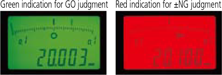

SPECIFICATIONS
Metric
| Order No.* | Range | Resolution | Accuracy** |
|---|---|---|---|
| 543-551 | 25mm |
0.001mm, 0.01mm |
0.003mm |
| 543-557 | 50mm | 0.003mm | |
| 543-553 | 50mm | 0.006mm |
* To denote your AC power cable add the following suffixes to the order No.: A for UL/CSA, D for CEE, DC for CCC, E for BS, K for KC, No suffix is required for JIS/100V
**Quantizing error of ±1 count is excluded.
Inch/Metric
| Order No.* | Range | Resolution | Accuracy** |
|---|---|---|---|
| 543-552 | 1” /
25.4mm |
.00005”, .0001”, .0005”, .001”, 0.001mm, 0.01mm |
.00012” /
0.003mm |
| 543-558 | 2” /
50.8mm |
.00012” /
0.003mm |
|
| 543-554 | 2” /
50.8mm |
.00024” /
0.006mm |
* To denote your AC power cable add the following suffixes to the order No.: A for UL/CSA, D for CEE, DC for CCC, E for BS, K for KC, No suffix is required for JIS/100V
**Quantizing error of ±1 count is excluded.
DIMENSIONS

Note 1: Dimensions of the inch (ANSI/AGD Type) dial indicator partly differ from those of the metric (ISO/JIS Type) indicator.
Note 2: Inch (ANSI/AGD Type) dial indicators are provided with a stem of 3/8″ dia. and #4-48UNF thread mount for the contact point.
Technical Data
Resolution: 0.01mm/0.001mm or .00005”/.0001”/.0005
”/.001”/0.001mm/0.01mm
Display: 6-digit LCD, sign, and analog bar with 2-color
backlight
Scale type: ABSOLUTE electrostatic linear encoder
Max. response speed: Unlimited
Measuring force: 1.8N or less (25.4mm models)
2.3N or less (50.8mm models)
Spindle orientation: Between the spindle pointing vertically
downward to the spindle horizontal
Stem dia.: 8mm (ISO/JIS type) or 3/8” (ANSI/AGD type)
Power supply: 9V DC (via AC adaptor) 06AEG302
Lifting lever: 137693
* To denote your AC power cable add the following
suffixes to the order No.: A for UL/CSA, D for CEE, DC
for CCC, E for BS, K for KC, No suffix is required for
JIS/100V
Functions
Preset, Zeroset, GO/±NG judgment, Max/Min value hold,
Runout measurement, Resolution switching,
Counting direction switching, Power ON/OFF, Data output,
inch/mm conversion (inch/mm models)
Alarm: Counting value composition error, Overflow
error, Tolerance limit setting error
Optional Accessories
• Lifting cable: No.540774 (stroke 25.4mm)
• Auxiliary spindle spring:
No.02ACA571 (25.4mm/1” models)*
No.02ACA773 (50.8mm/2” models)*
• Lug-on-center back:
No.101040 (ISO/JIS type)
No.101306 (ASME/ANSI/AGD type)
* Required when orienting the indicator upside down.
• SPC cable:
No.936937 (1m)
No.965014 (2m)
• USB Input Tool Direct (2m) : No.06ADV380F
• Connecting Cables for U-WAVE-T (160mm) :
No.02AZD790D
For footswitch: No.02AZE140D
Refer to page F-60 for details.
• Digimatic Mini-Processor DP-1VR: 264-504
• Contact points for Mitutoyo’s dial indicators *
• Interchangeable backs for Series 2 models*
• Measuring stands
* 4 Refer to pages F-46 to F-49 for details.
* 5 Refer to page F-50 for details.
Application
Difference/Runout measurement
Example: Indicator travel from points A to D
Difference (or Total Runout) is displayed as A. Dimensions B (maximum value) and C (minimum value) can be recalled from memory with a simple key sequence.


SPECIFICATIONS
Metric
| Order No.* | Range | Resolution | Accuracy** |
|---|---|---|---|
| 543-561 | 30.4mm | 0.0005mm,
0.001mm |
0.0015mm |
| 543-563 | 60.9mm | 0.0025mm |
* To denote your AC power cable add the following suffixes to the order No.: A for UL/CSA, D for CEE, DC for CCC, E for BS, K for KC, No suffix is required for JIS/100V
** Quantizing error of ±1 count is excluded.
Inch/Metric
| Order No.* | Range | Resolution | Accuracy** |
|---|---|---|---|
| 543-562 | 1.2” / 30.4mm | .00002”,
.00005”, .0001”, 0.0005mm, 0.001mm |
.00006” /
0.0015mm |
| 543-564 | 2.4” / 60.9mm | .0001” /
0.0025mm |
* To denote your AC power cable add the following suffixes to the order No.: A for UL/CSA, D for CEE, DC for CCC, E for BS, K for KC, No suffix is required for JIS/100V
DIMENSIONS

Note 1: Dimensions of the inch (ANSI/AGD Type) dial indicator partly differ from those of the metric (ISO/JIS Type) indicator.
Note 2: Inch (ANSI/AGD Type) dial indicators are provided with a stem of 3/8″ dia. and #4-48UNF thread mount for the contact point.
( ): for 30.4mm model

Technical Data
Display: 7-digit LCD, sign, and analog bar with 2-color backlight
Power supply: 6V DC (via AC adaptor) 06AEG180
* To denote your AC power cable add the following suffixes to the
order No.: A for UL/CSA, D for CEE, DC for CCC, E for BS, K for KC,
No suffix is required for JIS/100V
Positional detection method: Photoelectric-type reflection linear encoder
Maximum response speed: 1000mm/sec
Measuring force: 2.0N or less (30.4mm/1.2″type)
2.5N or less (60.9mm/2.4″type)
Spindle orientation: Between the spindle pointing vertically
downward to the spindle horizontal
Standard contact point: 901312 (ISO/JIS type)
21BZB005 (ANSI/AGD type)
Lifting lever: No.137693
Functions
Zero set, Preset, GO/±NG judgement
Max/Min value hold, Runout measurement
Resolution switching
Counting direction switching
Data output, Data hold, Function lock
inch/mm conversion (inch/mm models)
Alarm: Over speed error, Setting error, Overflow error
Optional accessories
• Lifting
Lifting knob : No.21EZA101
Lifting cable : No.540774 (stroke 30 mm)
• Lug-on-center back:
No.101040 (ISO/JIS type)
No.101306 (ASME/ANSI/AGD type)
• Remote controller : No.21EZA099
• RS-232 Connecting cable (2m) : No.21EAA131
• SPC Cable:
No.936937 (1m)
No.965014 (2m)
• USB Input Tool Direct (2m) : No.06ADV380D
• Connecting Cables for U-WAVE-T (160mm) :
No.02AZD790D
For footswitch : No.02AZE140D
Refer to page F-60 for details.
• Digimatic Mini-Processor DP-1VR: 264-504
• Contact points for Mitutoyo’s dial indicators (Refer to pages F-46 to F-49 for details.)
• Granite comparator stand: 215-156-10
• Comparator stand: 215-505-10

SPECIFICATIONS
Metric
| Order No. (w/ lug, flat-back) | Range | Resolution | Accuracy* | Measuring force | |
|---|---|---|---|---|---|
| — | 575-121 | 25.4mm | 0.01mm | 0.02mm | 1.8N or less |
Inch/Metric
| Order No. (w/ lug, flat-back) | Range | Resolution | Accuracy* | Measuring force | |
|---|---|---|---|---|---|
| — | 575-122 | 1” / 25.4mm | .0005”/0.01mm | .001” / 0.02mm | 1.8N or less |
| — | 575-123 | ||||
*Quantizing error of ±1 count is excluded
*Flat back only
DIMENSIONS

Note 1: Dimensions of the inch (ANSI/AGD Type) dial indicator partly differ from those of the metric (ISO/JIS Type) indicator.
Note 2: Inch (ANSI/AGD Type) dial indicators are provided with a stem of 3/8″ dia. and #4-48UNF thread mount for the contact point.
Technical Data
Accuracy: Refer to the list of specifications (Excluding quantizing error of ±1 count)
Resolution: 0.01mm, .0005″/0.01mm
Display: 5-digit and sign
Scale type: ABSOLUTE electrostatic linear encoder
Max. response speed: Unlimited (Measurement by scanning cannot be performed)
Measuring force: Refer to the list of specifications
Stem dia.: 8mm (ISO/JIS type) or 3/8” (ANSI/AGD type)
Standard contact point: 901312 (ISO/JIS type)
21BZB005 (ANSI/AGD type)
Battery: SR44 (1 pc.), 938882 for initial
operational checks (standard accessory)
Battery life: Approx. 20,000 hours of continuous use
Dust/Water protection level: IP42
Lifting lever: 137693
Function
Origin-set (Zeroset), Counting direction switching,
Power ON/OFF, Data output,
inch/mm conversion (inch/mm models)
Alarm: Low voltage, Counting value composition error
Optional Accessories
• Spindle lifting cable (stroke: 10mm) : No.540774
• SPC Cable:
No.905338 (1m)
No.905409 (2m)
• USB Input Tool Direct (2m) : No.06ADV380F
• Connecting Cables for U-WAVE-T (160mm):
No.02AZD790F
For footswitch : No.02AZE140F
Refer to page F-60 for details.
• Digimatic Mini-Processor DP-1VR: 264-504
• Contact points for Mitutoyo’s dial indicators (Refer to pages F-46 to F-49 for details.)
• Measuring stands (Refer to page F-79 to F-85 for details.)